
This portion of the CPU is responsible for all of the arithmetic, logic, and boolean functionality. It also includes a flags register as well as a conditional jump logic module. Internally it uses the A and B data buses to move local data around. It is also connected to the main 8-bit data bus to transfer values to the accumulator and operand registers as well as output the result of the given function. It is also used to restore the flags register during an interrupt return instruction.
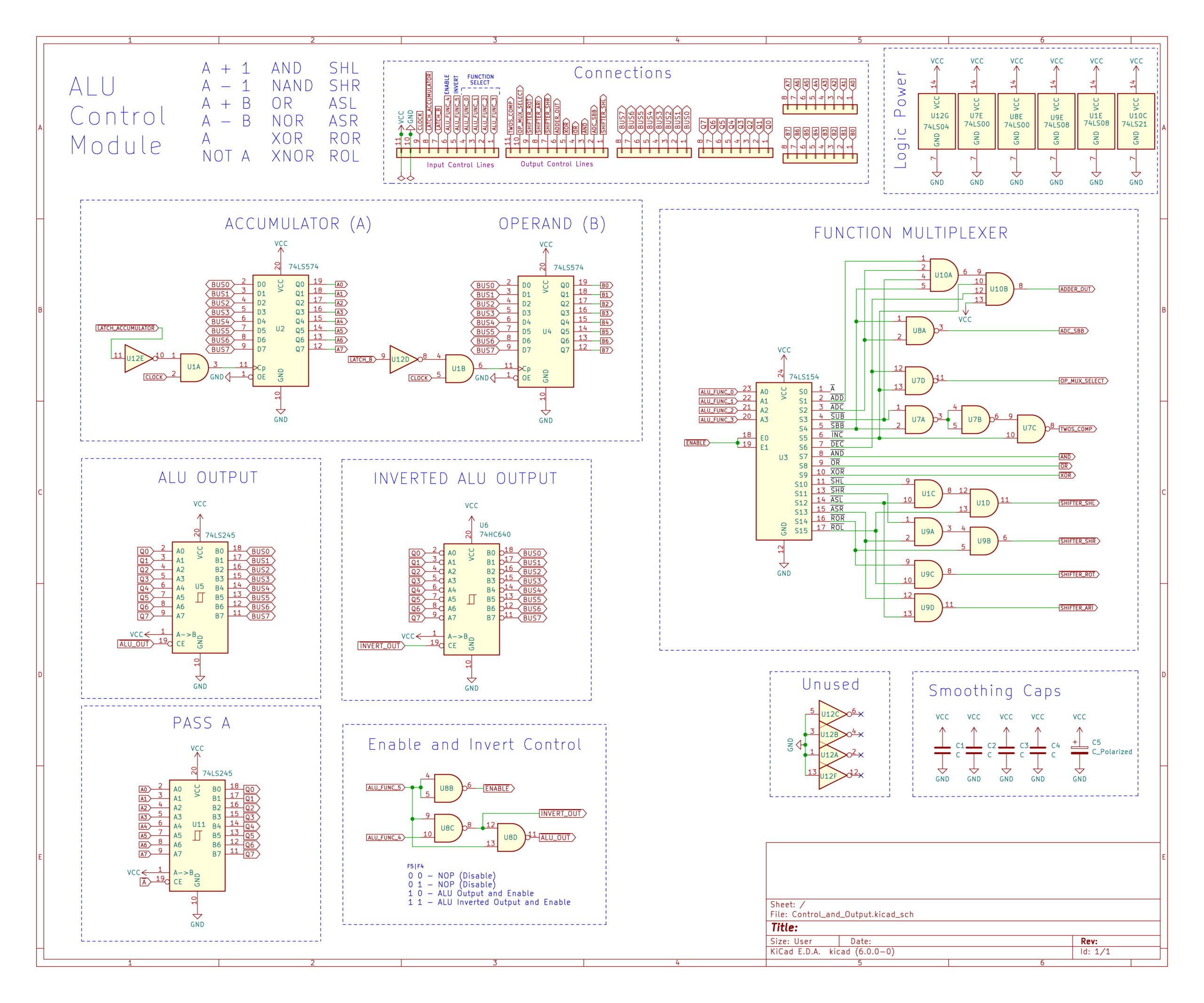
ALU Control Module
| FUNCTION | DESCRIPTION | Flags Affected | CONTROL |
PASS A | Outputs the accumulator(A) to the data bus | 0x20 | |
INC | Increment, A + 1 | CF, SF, OF, ZF | 0x25 |
DEC | Decrement, A – 1 | CF, SF, OF, ZF | 0x26 |
ADD | Addition, A + B | CF, SF, OF, ZF | 0x21 |
ADC | Addition w/ Carry, A + B + Carry Flag | CF, SF, OF, ZF | 0x22 |
SUB | Subtract, A – B | CF, SF, OF, ZF | 0x23 |
SBB | Subtract w/ Carry, A – B – Carry Flag | CF, SF, OF, ZF | 0x24 |
NOT | Invert A, ~A | 0x30 | |
AND | Boolean AND, A & B | SF, ZF, OF: Cleared, CF: Cleared | 0x27 |
NAND | Boolean NAND, ~(A & B) | SF, ZF, OF: Cleared, CF: Cleared | 0x35 |
OR | Boolean OR, A | B | SF, ZF, OF: Cleared, CF: Cleared | 0x28 |
NOR | Boolean NOR, ~(A | B) | SF, ZF, OF: Cleared, CF: Cleared | 0x38 |
XOR | Boolean XOR, A ^ B | SF, ZF, OF: Cleared, CF: Cleared | 0x29 |
XNOR | Boolean XNOR, ~(A ^ B) | SF, ZF, OF: Cleared, CF: Cleared | 0x39 |
SHL | Shift Left, A << 1 | CF: Bit shifted out, SF, ZF, OF | 0x2a |
SHR | Shift Right, A >> 1 | CF: Bit shifted out, SF, ZF, OF | 0x2b |
ASL | Signed Arithmetic Shift Left, A * 2 | CF: Bit shifted out, SF, ZF, OF | 0x2c |
ASR | Signed Arithmetic Shift Riht, A / 2 | CF: Bit shifted out, SF, ZF, OF | 0x2d |
ROR | Rotate Right | CF: Bit shifted out, SF, ZF, OF | 0x2e |
ROL | Rotate Left | CF: Bit shifted out, SF, ZF, OF | 0x2f |
CMP | Compare, same as SUB but does not latch Flags | 0x23* | |
TST | Test, same as AND but does not latch Flags | 0x27* |
Accumulator and Operand Registers
Latch Accumulator– Loads the value present on the data bus into the Accumulator (A) Register to be used by the various ALU functions.
Latch Operand– Loads the value present on the data bus into the Operand (B) Register to be used by the various ALU functions.
Control Unit Schematic Drawing
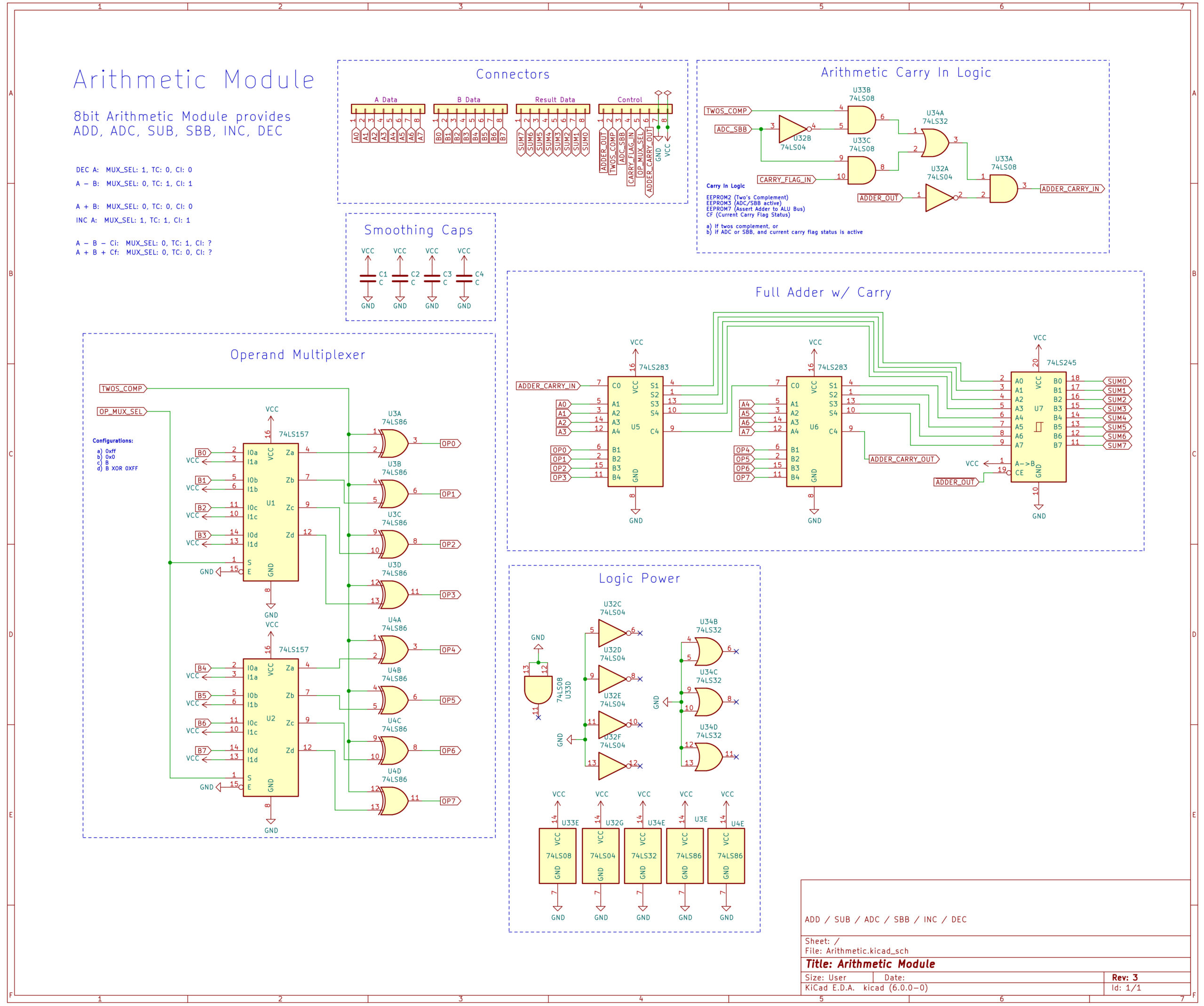
Arithmetic Module
This module is built with two 4-bit Full Adders to perform addition on two 8-bit values. It uses two’s complement for Subtraction by XOR’ing the operand (B) with 1 and adding 1. It also has the ability to increment or decrement the accumulator.
Arithmetic Control Truth Table
| Instruction | Mux | Two’s Comp | Carry In |
| A + B | 0 | 0 | 0 |
| A – B | 0 | 1 | 1 |
| A + B + Carry | 0 | 0 | Carry Flag Value |
| A – B – Carry | 0 | 1 | Carry Flag Value |
| INC ( A + 1) | 1 | 1 | 1 |
| DEC ( A – 1) | 1 | 0 | 0 |
Arithmetic Examples
| Function | A | B | CF | Result |
| ADD | 0b0011 | 0b0001 | n.c. | 0b0100 |
| ADC | 0b0011 | 0b0001 | 1 | 0b0101 |
| SUB | 0b0011 | 0b0001 | n.c. | 0b0010 |
| SBB | 0b0011 | 0b0001 | 1 | 0b0001 |
| INC | 0b0011 | n.c. | n.c. | 0b0100 |
| DEC | 0b0011 | n.c. | n.c. | 0b0010 |
Arithmetic Schematic Drawing
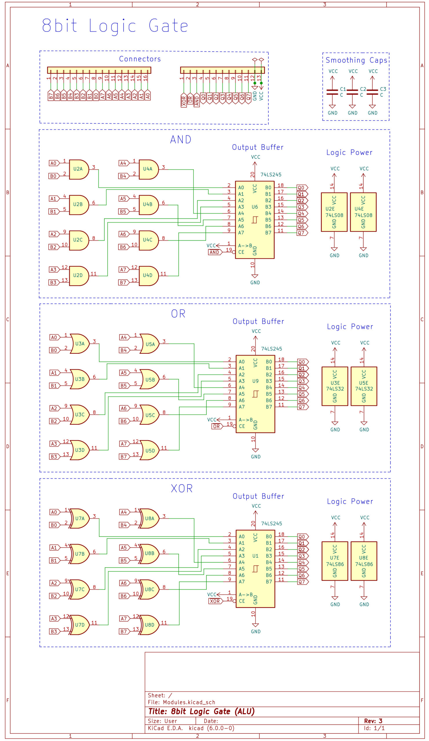
Logic Gate Module
This module is responsible for executing logical bitwise operations. It contains only the AND, OR, and NOR functions. To acheive NAND, NOR, and XNOR the result is inverted at the ALU control unit.
Logic Gate Examples
| Function | A | B | Result |
| AND | 0b0101 | 0b0011 | 0b0001 |
| NAND* | 0b0101 | 0b0011 | 0b1110 |
| OR | 0b0101 | 0b0011 | 0b0111 |
| NOR* | 0b0101 | 0b0011 | 0b1000 |
| XOR | 0b0101 | 0b0011 | 0b0110 |
| XNOR* | 0b0101 | 0b0011 | 0b1001 |
*1 – Uses same function, however, the invert control bit is set to active. ie. and => nand
Logic Gate Schematic Drawing
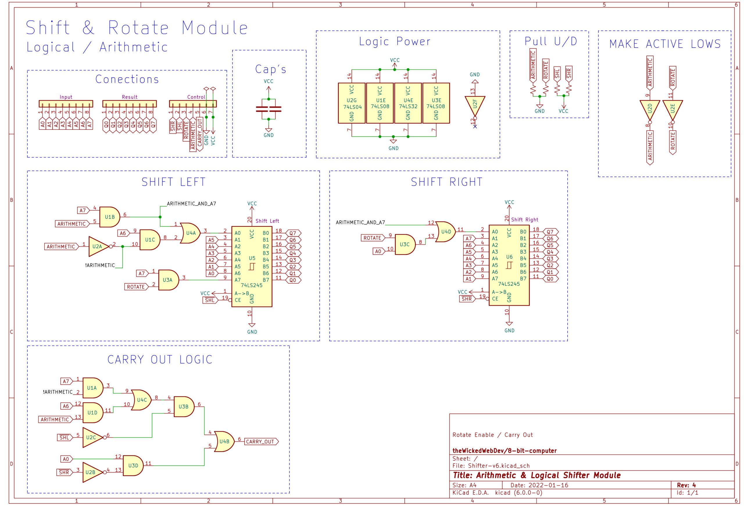
Shift & Rotate Module
This module provides the ability to shift bits to the left or right. Can be done logically or arithmetically. The logical shift is unsigned (ignores MSB), whereas Arithmetic Shift is signed, and maintains the most significant bit. This is the equivalent of multiplying/dividing by 2.
Shift & Rotate Truth Table
| Function | Shift Right | Shift Left | Rotate | Arithmetic |
| SHL | 1 | 0 | 1 | 1 |
| SHR | 0 | 1 | 1 | 1 |
| ASL | 1 | 0 | 1 | 0 |
| ASR | 0 | 1 | 1 | 0 |
| ROR | 0 | 1 | 0 | 1 |
| ROL | 1 | 0 | 0 | 1 |
Shift & Rotate Examples
| Function | Operand | Result |
| SHL | 0b10001001 | 0b00010010 |
| SHR | 0b10001001 | 0b01000100 |
| ASL | 0b10001001 | 0b10010010 |
| ASR | 0b10001001 | 0b11000100 |
| ROR | 0b10001001 | 0b11000100 |
| ROL | 0b10001001 | 0b00010011 |
Shift & Rotate Schematic Drawing
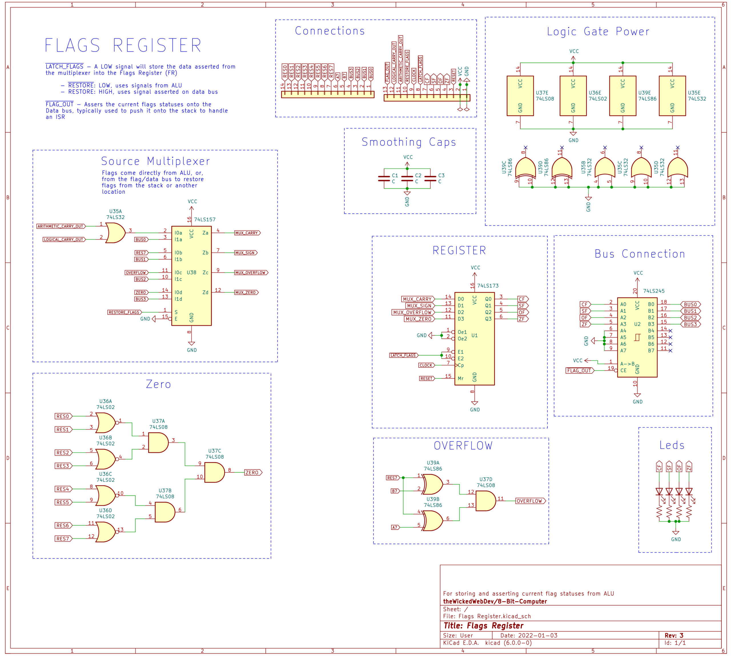
Flags Register
Bit Order on Data Bus
| BIT 3 | BIT 2 | BIT 1 | BIT 0 |
| Zero (ZF) | Overflow (OF) | Sign (SF) | Carry (CF) |
Flags Out– Asserts the flags register onto the data bus.
Flags In– Latches the flag’s register with calculated values based on the alu function’s result. This is active for all ALU functions except CMP and TST
Restore Flags– Used in conjunction with Flags In, this will latch the register with values asserted on the data bus. This is normally used when returning from an interrupt and popping the flags off of the stack.
Flags Regsiter Truth Table
| Flags Out | Flags In | Restore Flags | Description |
| 1 | 1 | n.c. | NOP |
| 0 | 1 | n.c. | Assert Flags to Data Bus |
| 1 | 0 | 0 | Latch flags from ALU. Used with mostly all ALU functions. |
| 1 | 0 | 1 | Latches/Restores flag data from 8-bit data bus. Normally used while returning from interrupt. |
Flags Register Schematic Drawing
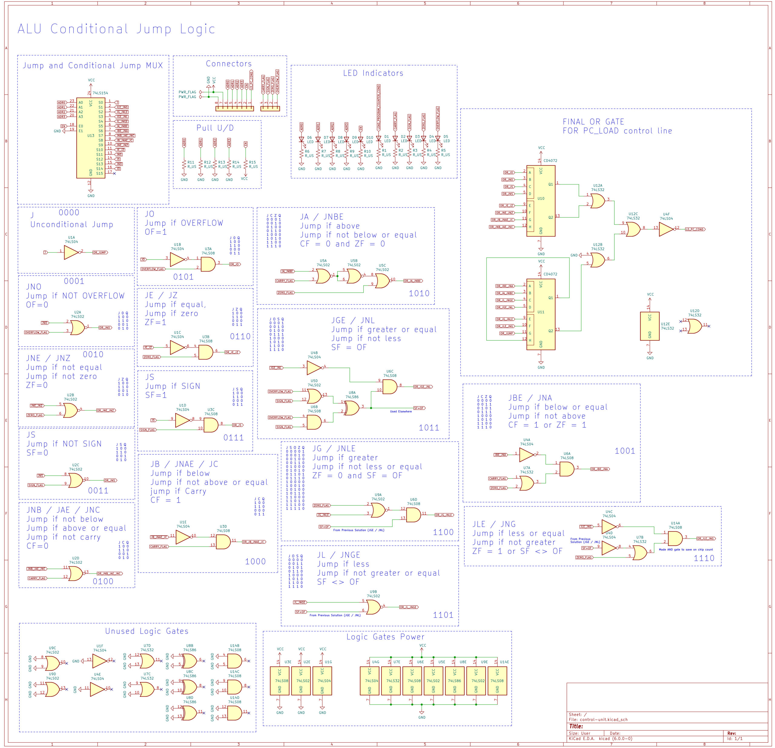
Conditional Jump Logic
This module provides all of the conditions for calculating jumps based on ALU Flags. It uses a 4-bit control bus with enable, which is connected to the main CPU’s microcode control logic, the ALU flags and outputs a single control line which is LOW if a jump is active.
| Mnemonic | Description | Flags | Control |
jp | Jump | n/a | 0x0 |
jle / jng | Jump if Less Than or Equal / Jump Not Greater | ZF = 1 or SF <> OF | 0x1 |
jg / jnle | Jump if Greater / Jump if Not Less Than or Equal | ZF = 0 and SF = OF | 0x2 |
jge / jnl | Jump if Greater Than or Equal / Jump if Not Lower | SF = OF | 0x3 |
jl / jnge | Jump if Less Than / Jump if Not Greater Than or Equal | SF <> OF | 0x4 |
ja / jnbe | Jump if Above / Jump if Not Below | CF = 0 and ZF = 0 | 0x5 |
jbe / jna | Jump if Below / Jump if Not Above | CF = 1 or ZF = 1 | 0x6 |
jnb / jae / jnc | Jump if not below / Jump if above or equal / Jump if not carry | CF = 0 | 0x7 |
jb / jnae / jc | Jump if below / Jump if not above or equal / Jump if carry | CF = 1 | 0x8 |
jne / jnz | Jump if not equal / Jump if not zero | ZF = 0 | 0x9 |
je / jz | Jump if equal / Jump if zero | ZF = 1 | 0xa |
jns | Jump if not sign | SF = 0 | 0xb |
js | Jump if sign | SF = 1 | 0xc |
jno | Jump if not overflow | OF = 0 | 0xd |
jo | Jump if overflow | OF = 1 | 0xe |
Conditional Jump Logic Schematic Drawing