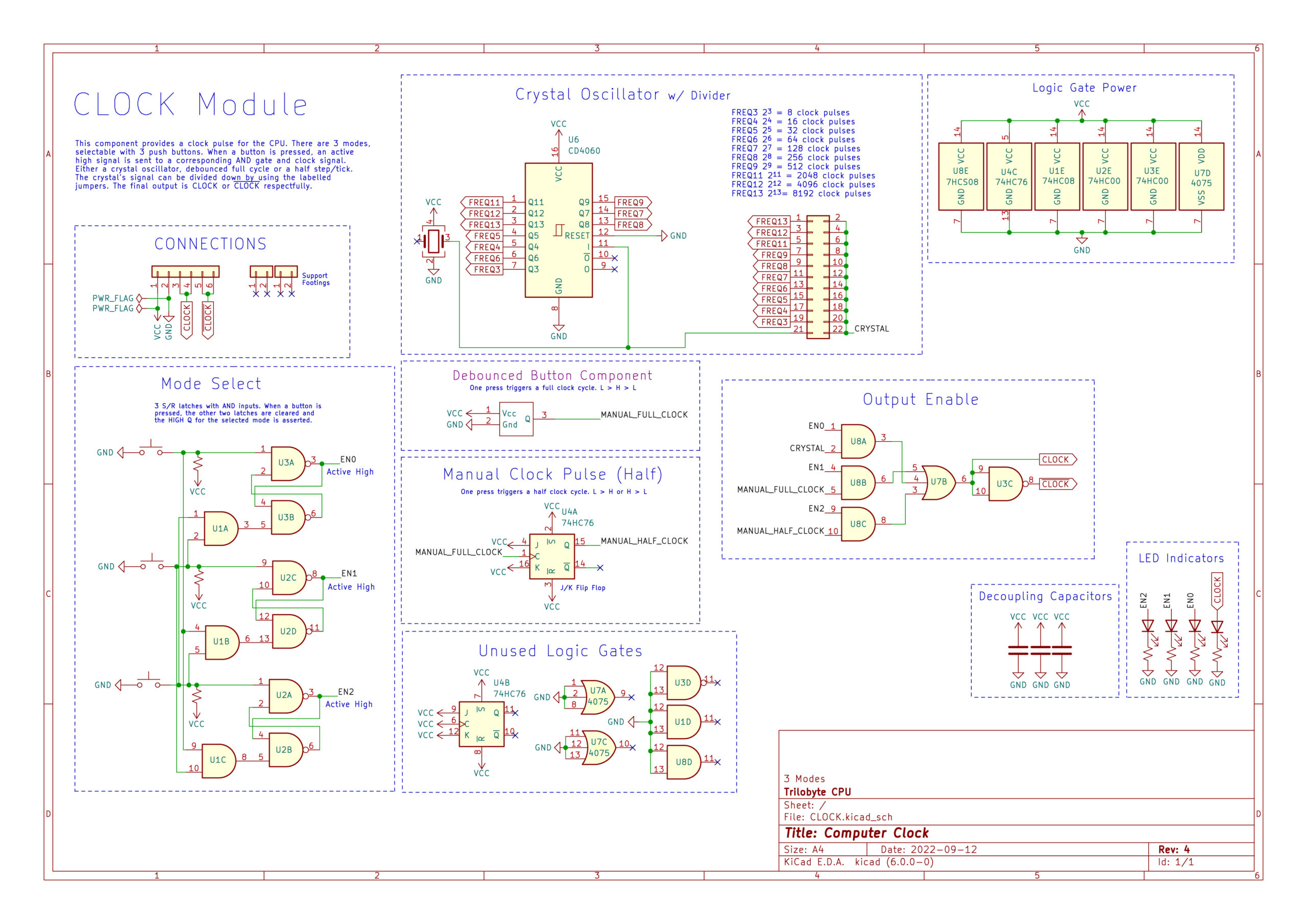
This module provides a square wave throughout the entire CPU which allows it to synchronize all of the operations, instructions, or calculations. During normal operation of the computer, this will be set to the full frequency of the crystal oscillator, however; when a user wants to debug there is the capability of slowing the clock down and switching it to a manual mode.
Control Function Table
Crystal Btn
Full Btn
Half Btn
Debounced Btn
Description
Push
X
X
X
Enables the Crystal Oscillator output
X
Push
X
X
Enables the Full Clock Cycle output
X
X
Push
X
Enables the Half Clock Cycle output
1
X
X
X
Auto Clock Pulse at a frequency set by header pins