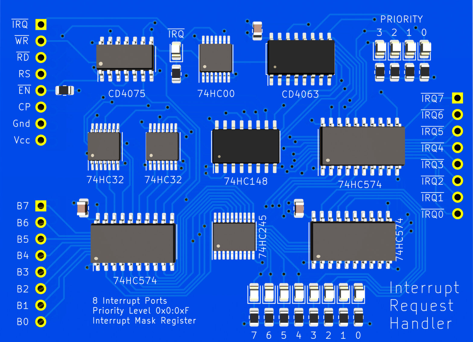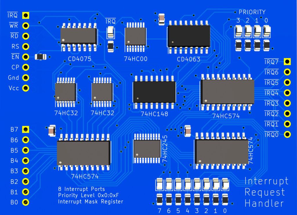
Interrupt requests come from various sources such as internal timers or I/O devices. There are a total of 8 unique interrupt requests that can be made. They can be prioritized and masked, which gives the user control over what interrupts can fire and when. The ISR[7] will only be executed when all other ISRs have been completed. It has the lowest priority. ISR[0], if un-masked, will always have the highest priority and be run first.
Mask
Using the interrupt mask register, you are able to disable any interrupt request from reaching the CPU. This also means that if a disabled interrupt is triggered from an external I/0 device, it will never get latched.
This is done by setting the corresponding BIT[0..7] to HIGH.
| BIT7 | BIT6 | BIT5 | BIT4 | BIT3 | BIT2 | BIT1 | BIT0 |
|---|---|---|---|---|---|---|---|
| IRQ7 | IRQ6 | IRQ5 | IRQ4 | IRQ3 | IRQ2 | IRQ1 | IRQ0 |
Example:

Priority
This register sets a “cutoff” level for disabling any interrupt below a specified priority level. This differs from masking because it will still allow deprioritized interrupts to be latched, but they are just prevented from causing an interrupt request.
| BIT3 | BIT2 | BIT1 | BIT0 |
|---|---|---|---|
| P3 | P2 | P1 | P0 |
When IRQ[x] < PRIORITY an interrupt request is initiated.
- A Priority 8+ level will enable all IRQs
- A Priority 7 level, will enable IRQ[0..6]
- A Priority 6 level, will enable IRQ[0..5]
- A Priority 5 level, will enable IRQ[0..4]
- A Priority 4 level, will enable IRQ[0..3]
- A Priority 3 level, will enable IRQ[0..2]
- A Priority 2 level, will enable IRQ[0, 1]
- A Priority 1 level, will enable IRQ[0]
A Priority 0 level, will disable all IRQs
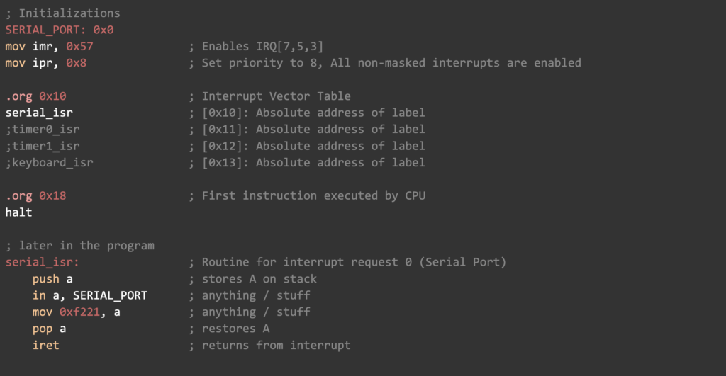
Example:

Example Usage
Lets say you want to enable 4 interrupts, but you want to be sure that while executing a specific interrupt service routine, you temporarily disable the CPU from triggering another interrupt request. You can do the following:
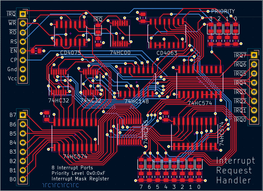
PCB Gerber/Traces
Schematic Diagram
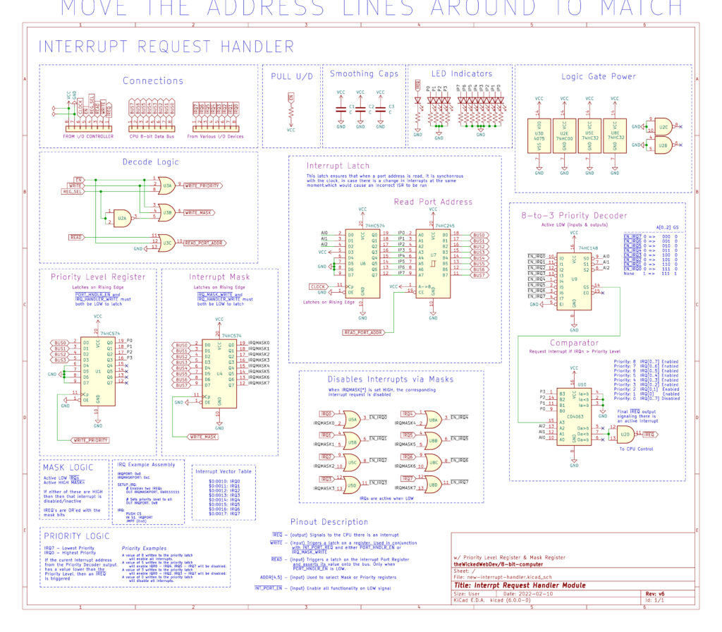
Parts & Components List
| PART # | DESCRIPTION | QTY | SHEET | LINK |
| 74HC32 | Quad 2-input OR gates | 2 | DATA | Mouser |
| 74HC00 | Quad 2-input NAND gates | 1 | DATA | Mouser |
| 74HC574 | 8-Bit, Edge-Triggered, flip-flop’s | 3 | DATA | Mouser |
| 74HC245 | 8-bit, Tri-State Transceiver | 1 | DATA | Mouser |
| CD4075 | CMOS Triple 3-Input OR Gate | 1 | DATA | Mouser |
| 74HC148 | 4 to 16 line, decoder | 1 | DATA | Mouser |
| CD4063 | 4-Bit Magnitude Comparator | 1 | DATA | Mouser |
| – | Ceramic Capacitor | 3 | – | – |
| – | Resistors | 14 | – | – |
| – | Light Emitting Diodes (LED) | 13 | – | – |
| – | Header Pins | – | – |

