
The module provides the CPU with 2 megabytes of volatile memory and 32k of persistent EEPROM memory.
Note: The lower 32k of address space is not available to RAM, it is unreachable.
EEPROM (32k)
$0000:$7fff
This is the memory that is used on startup to start running the program.
Reserved Address Space
- $0:0: Initial program code instruction called after reset/boot
Interrupt Vector Table (IVT)
- $0:f0: IRQ0
- $0:f1: IRQ1
- $0:f2: IRQ2
- $0:f3: IRQ3
- $0:f4: IRQ4
- $0:f5: IRQ5
- $0:f6: IRQ6
- $0:f7: IRQ7
- $0:ff: Interrupt Service Routine (ISR)
- $0:fe: Reset
RAM (2Mb)
$8000:$20000
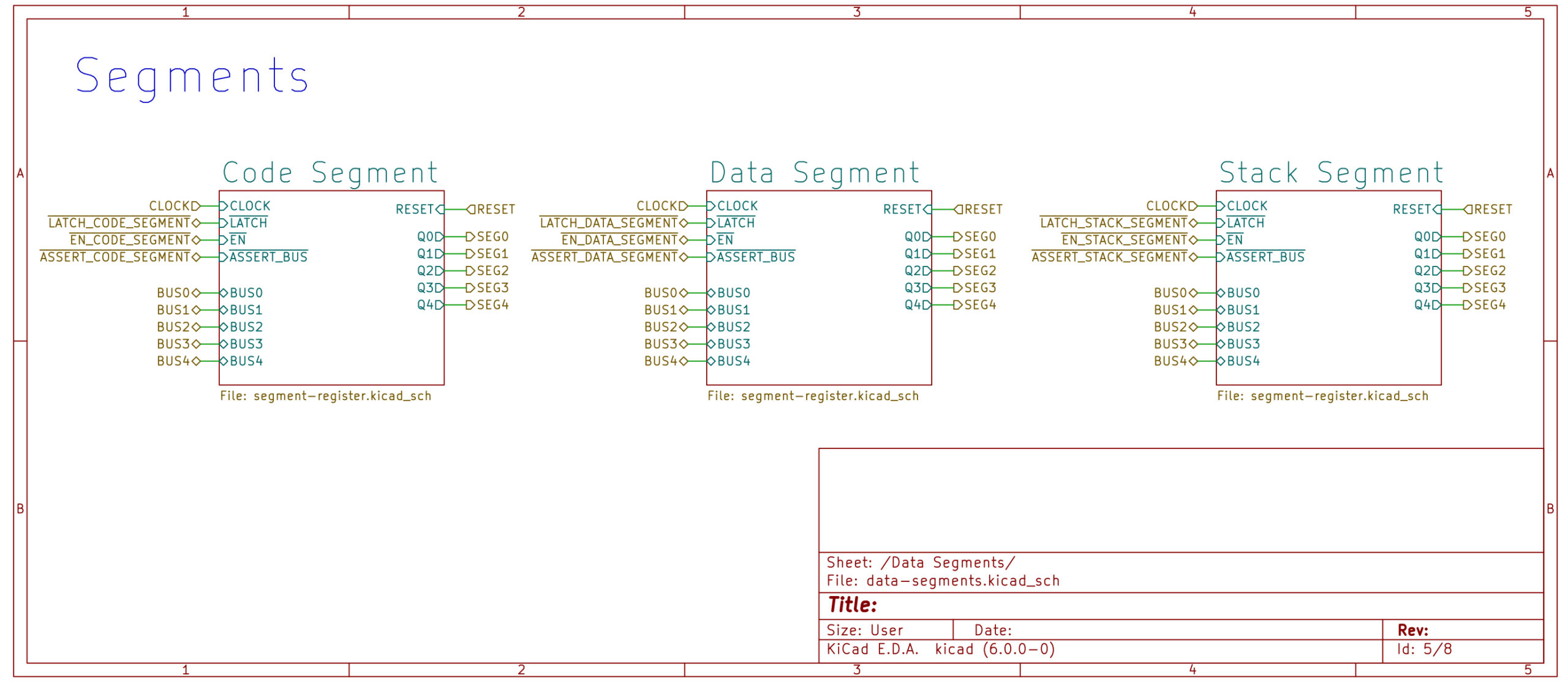
Segments / Paged
Each segment register is 5-bits wide and allows the user to access the entire range of space in memory. 16-bits from address bus and the additional 3-bits (+2 bits for decoding chip enables) to make a 19-bit address.
Each segment can latch data from the lower 5-bits of the data bus as well as assert its contents out.
Code Segment (CS)
This is active when fetching the next instruction. It is only changed by a far jmp instruction and cannot be manipulated by mov
Data Segment (DS)
This is active during any read‘s or write‘s to Memory (excluding program code). This can be set using mov ds, 0xf
Stack Segment (SS)
This is active when executing a PUSH or POP instruction to and from the stack. This can be set using mov ss, 0xf
Read/Write Memory Control Truth Table
| Address | Segment[0..4] | Read | Write | Use Code | Use Data | Use Stack | Description |
| n.c. | n.c. | 1 | 1 | 1 | 1 | 1 | NOP |
| <= 0x7ffff | 0x0 | 0 | n.c. | 0 | 1 | 1 | Read Code EEPROM |
| <= 0x7ffff | 0x0 | 0 | n.c. | 1 | 0 | 1 | Read Data EEPROM |
| 0x0…0x20000 | 0x1…0x1f | 0 | 1 | 0 | 1 | 1 | Read Code RAM |
| 0x0…0x20000 | 0x1…0x1f | 0 | 1 | 1 | 0 | 1 | Read Data RAM |
| 0x0…0x20000 | 0x1…0x1f | 0 | 1 | 1 | 1 | 0 | Read Stack RAM |
| >= 0x8000 | n.c. | 0 | 1 | 0 | 1 | 1 | Read Code RAM |
| >= 0x8000 | n.c. | 0 | 1 | 1 | 0 | 1 | Read Data RAM |
| >= 0x8000 | n.c. | 0 | 1 | 1 | 1 | 0 | Read Stack RAM |
| 0x0…0x20000 | 0x1…0x1f | 1 | 0 | 1 | 0 | 1 | Write Data RAM |
| >= 0x8000 | n.c. | 1 | 0 | 1 | 0 | 1 | Write Data RAM |
| 0x0…0x20000 | 0x1…0x1f | 1 | 0 | 1 | 1 | 0 | Write Stack RAM |
| >= 0x8000 | n.c. | 1 | 0 | 1 | 1 | 0 | Write Stack RAM |
Memory Segment & Address Control Truth Table
| CS In | CS Out | DS In | DS Out | SS In | SS Out | MAR In | Clock | Description |
| 1 | 1 | 1 | 1 | 1 | 1 | 1 | _/ | NOP |
| 0 | 1 | 1 | 1 | 1 | 1 | 1 | _/ | Latches Code Segment |
| 1 | 1 | 0 | 1 | 1 | 1 | 1 | _/ | Latches Data Segment |
| 1 | 1 | 1 | 1 | 0 | 1 | 1 | _/ | Latches Stack Segment |
| 1 | 0 | 1 | 1 | 1 | 1 | 1 | _/ | Assert Code Segment |
| 1 | 1 | 1 | 0 | 1 | 1 | 1 | _/ | Assert Data Segment |
| 1 | 1 | 1 | 1 | 1 | 0 | 1 | _/ | Assert Stack Segment |
| 1 | 1 | 1 | 1 | 1 | 1 | 0 | _/ | Latch Memory Address Register |
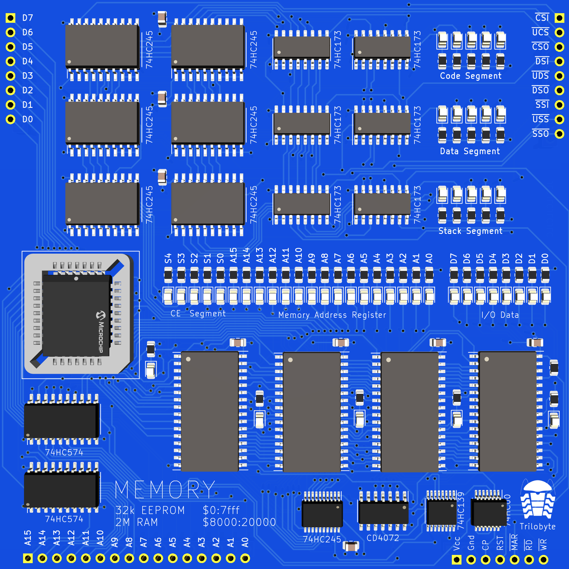
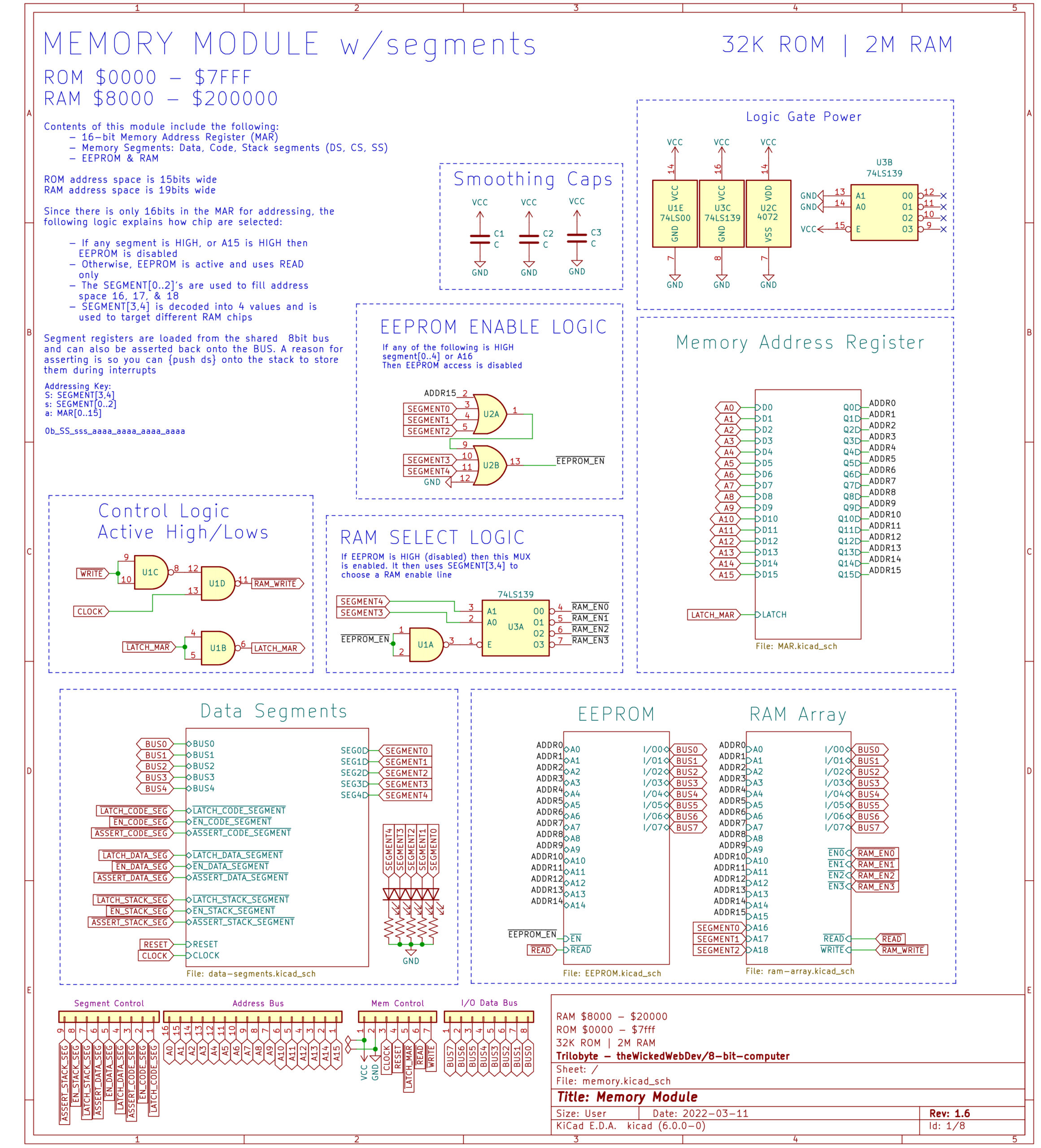
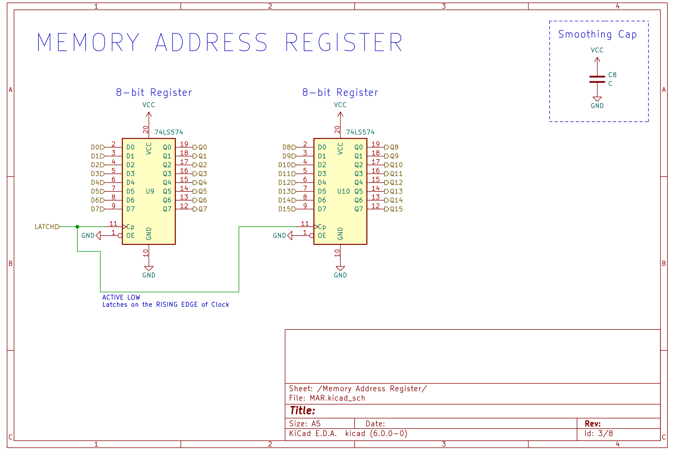
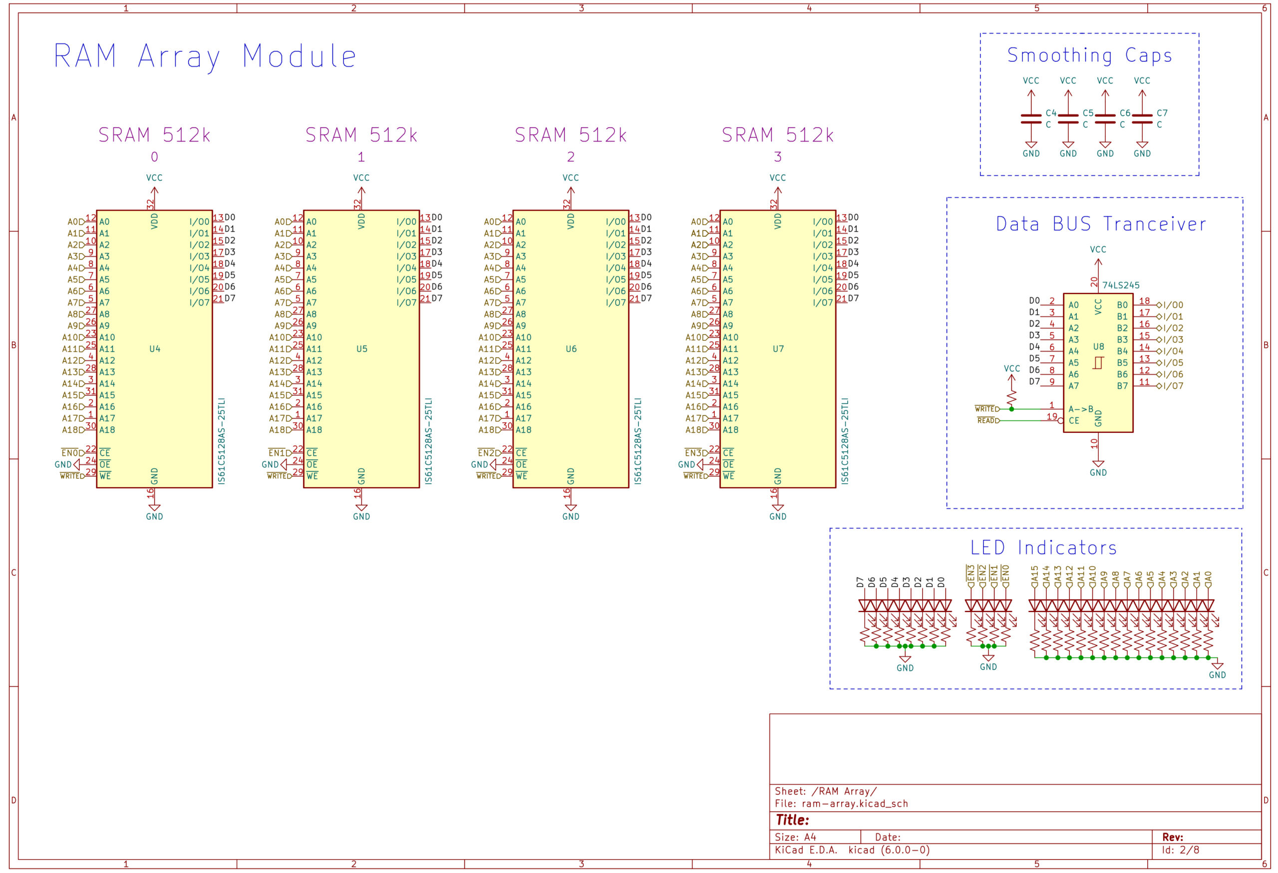
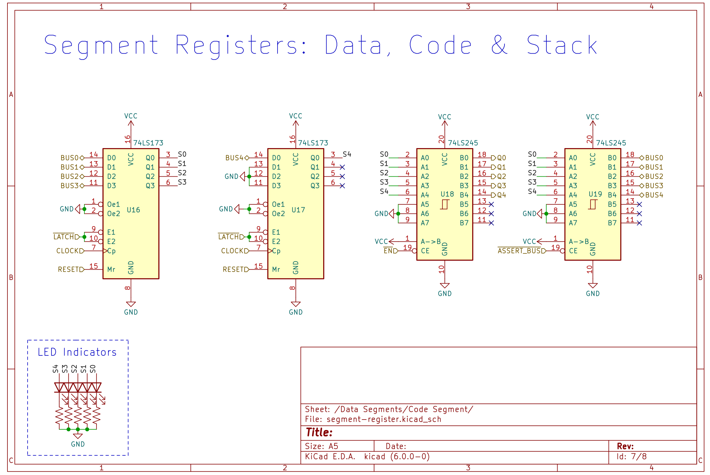
Schematics
Memory Module
Data Segment’s Schematic
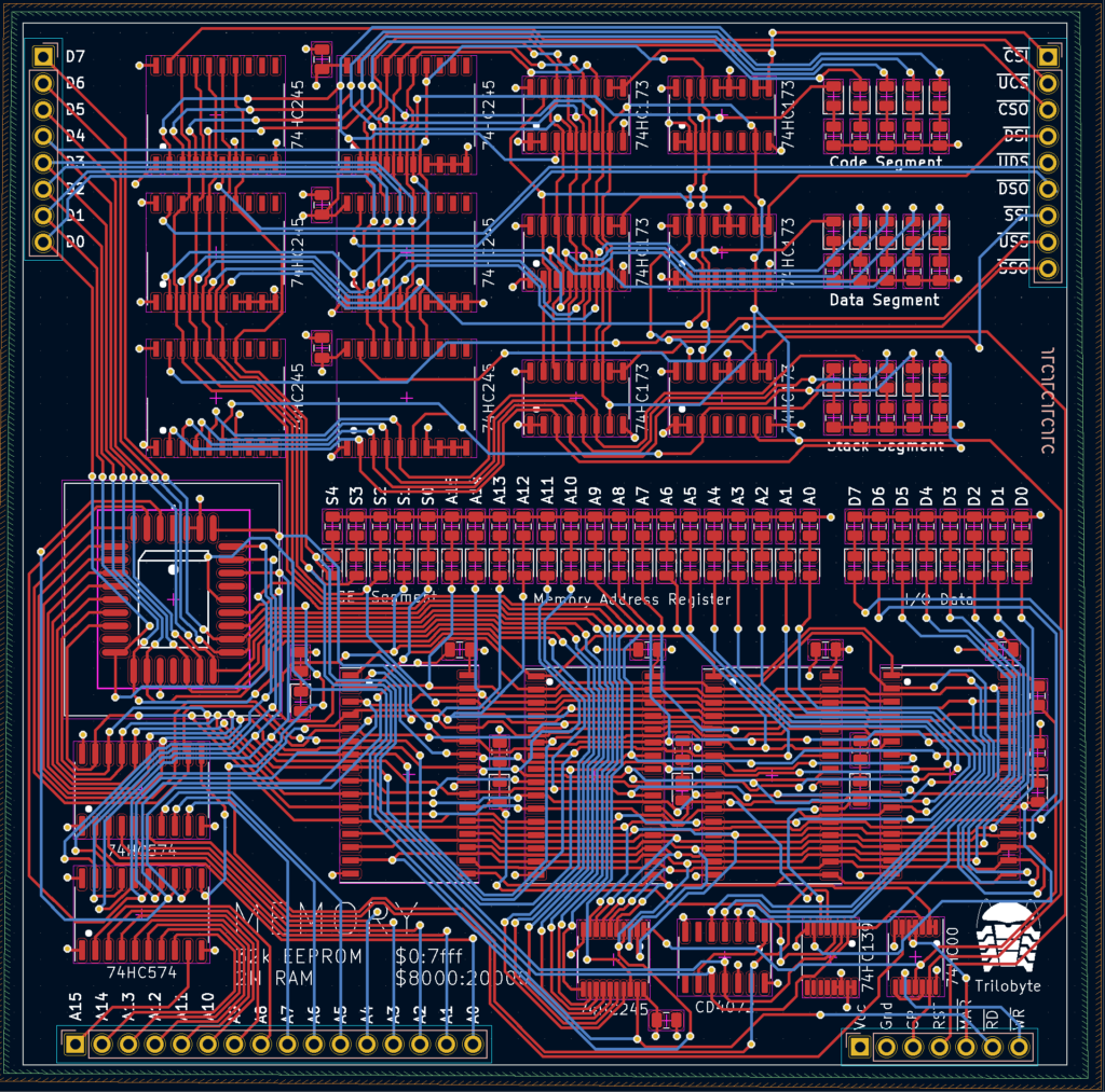
PCB Gerber/Traces
Parts & Components List
| PART # | DESCRIPTION | QTY | SHEET | LINK |
| IS61C5128AS-25TLI | 512K x 8 HIGH-SPEED CMOS STATIC RAM | 4 | DATA | Mouser |
| AT28C256 | 256K (32K x 8) Paged Parallel EEPROM | 1 | DATA | Mouser |
| 74HC574 | 8-Bit, Edge-Triggered, flip-flop’s | 2 | DATA | Mouser |
| 74HC173 | Quad D-Type Flip-Flop | 2 | DATA | Mouser |
| 74HC245 | 8-bit, Tri-State Transceiver | 7 | DATA | Mouser |
| CD4072 | Dual 4-Input OR gates | 1 | DATA | Mouser |
| 74HC139 | 4 to 16 line, decoder | 1 | DATA | Mouser |
| 74HC00 | Dual 4-input NAND gates | 1 | DATA | Mouser |
| – | Ceramic Capacitor | 8 | – | – |
| – | Resistor (LED) | 49 | – | – |
| – | Light Emitting Diodes (LED) | 49 | – | – |
| – | PLCC Socket, 32 pin – MOUSER | 1 | – | – |
| – | Header Pins | – | – | – |